Enigma
About This Kata
You will be designing a software emulator for a World War Two era Enigma device. Enigma was a mechanical encryption system used by Nazi Germany to secure military communications. German U-Boats (submarines) prowled the North Atlantic ocean during the war, and Hitler hoped that by sinking Allied shipping he could eventually starve Britain into surrender. Alan Turing, who is widely credited with the invention of the digital computer and therefore the entire discipline of Computer Science, was instrumental in breaking the Enigma codes. To do that, however, he had to understand how the machines worked and now, so do you.
This kata is about teaching the fractal nature of testing. Enigma consisted of numerous electro-mechanical components, each of which performs simple transformations on each letter in a message. The complexity of enigma arises from interaction of these components. In the course of this kata you will want to ensure that you are accurately simulating the sub-structures of each element (unit tests), the elements as a whole (component tests), the higher level interactions between those elements (integration tests), and finally the entire encryption stack of the Enigma machine (end to end tests).
What follows is a description of how a Enigma I machine worked. How you break that apart into objects, design patterns, and consequently testing layers is up to you.
How Enigma Works
Enigma has three major components we are concerned about. Each of these can be thought of as a layer with the encryption of each character making its way down, through the outermost layer to the innermost and then back out. As it passes through each layer, the character is changed. This is what gives rise to Enigma's enormous complexity. Let's examine the path of the encryption of a single character before diving into how each component works. You can find a visual depiction of this process here though the specific values shown may not correspond to the actual wiring of actual rotors.
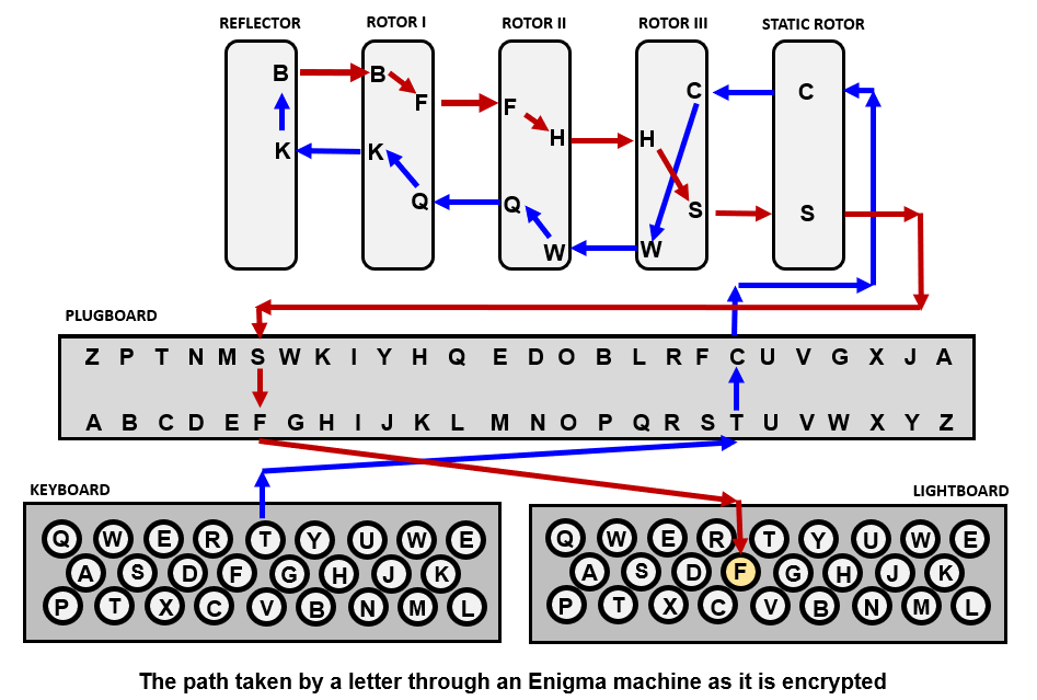
- A user types a single letter “T”
- The letter enters the Plugboard, where it is transposed to “C”
- The letter passes to the rotor assembly via the Static Rotor
- The letter enters Rotor III as “C” and exits as “W”
- The letter enters Rotor II as “W” and exits as “Q”
- The letter enters Rotor I as “Q” and exits as “K”
- The letter enters the Reflector as “K” and exits as “B” (NB: this is the innermost layer)
- The letter enters Rotor I as “B” and exits as “F”
- The letter enters Rotor II as “F” and exits as “H”
- The letter enters Rotor III as “H” and exits as “S”
- The letter exits the rotor assembly via the Static Rotor and is passed to the Plugboard
- The letter enters the Plugboard as “S” and exits as "F
- The “F” light illuminates, indicating that “T” was crypted to “F”
Now let's examine each component in turn.
Plugboard
The Plugboard allows the 1 to 1 swapping of letters as they pass in and out of the rest of the machine. Plugboard mappings are always symmetric so if A->Z then Z->A is also necessarily true. Historically Enigma had 10 possible plugboard mappings and all 10 were used every time (reducing the overall complexity of the machine) so your system should support at least 10 mappings.
Rotors
Rotors are the heart of Enigma. Each rotor had a fixed “wiring” representing a single Caesar substitution cypher. The rotors themselves were removable, so while most of the examples here involve the use of Rotor III in the far-right slot, Rotor II in the middle, and Rotor I on the left, a real Enigma machine allows the user to remove the rotors and swap them around. Further, as the name implies, the rotors turn with each keypress. Rotor advancement happens BEFORE encryption and, for the most part, progresses like an odometer, with the right-most rotor completing a rotation for each step the middle rotor executes. We'll come back to exceptions and complications later.
Reflectors
At the far left of the rotor assembly is a reflector. You can think of a reflector as a specialized type of rotor in which input and output happen on the same side. This means that, like the plugboard, reflectors are symmetrical. If the A->Q in the reflector then Q->A must also be true. This introduces a fatal flaw into enigma which is worth noting here: a letter can never crypt to itself. While later versions of enigma had moveable reflectors, this exercise will focus on a fixed reflector. Enigma I shipped with three reflectors called UKW-A, B, and C. You can find their wiring here (for more on how to make sense of this, see the Rotors in Detail section below)
| Reflector | Mapping |
|---|---|
| UKW-A | EJMZALYXVBWFCRQUONTSPIKHGD |
| UKW-B | YRUHQSLDPXNGOKMIEBFZCWVJAT |
| UKW-C | FVPJIAOYEDRZXWGCTKUQSBNMHL |
Rotors In Detail
The rotor is where the bulk of Enigma's complexity arises and so we're going to need to understand how it works in detail if we are to proceed.
Wiring
As noted above, rotors contain an internal wiring which is a hardware implementation of a Caesar substitution cypher. The cypher for the three rotors of the Enigma I is shown below:
| Rotor | Mapping |
|---|---|
| I | EKMFLGDQVZNTOWYHXUSPAIBRCJ |
| II | AJDKSIRUXBLHWTMCQGZNPYFVOE |
| III | BDFHJLCPRTXVZNYEIWGAKMUSQO |
From this table we can tell that Rotor I will encypher “A” to “E” and Rotor II will encypher “C” to “D.” Likewise, along the return path, Rotor II will encypher “S” to “E” and Rotor I will encypher “E” to “A.” In the course of the Second World War, Germany introduced many Enigma variants with numerous rotors. If you want to expand your own simulator to include them you can find their mappings here.
Offsets/Positions
As the rotors turn their position relative to the static rotor and the other rotors around them changes. For example, in its ordinary position, Rotor I will map A->E. With an offset of 1, however “A” will enter the rotor as “B.” Rotor 1 will map B->K and “K” will exit the rotor as "J".
Ringsettings
Enigma added additional complexity by allowing a user to rotate the wiring of the rotor within its housing during setup. This rotation was called the “Ringsetting” and is the logical inverse of Offsets. With a Ringsetting of “B” (or 1) and an Offset of “A” (or 0) Rotor I behaves as follows: “A” enters the rotor as “A” before being passed though to the “Z” entry point on the internal wiring. The wiring maps “Z” to “J” which is passed out to the rotor housing as “K” which exits the rotor as “K.”
Stepping
First, a quick note on how we discuss rotor positions. Rotor positions are usually written left to right like “ABC,” where the rotor in position “C” is the FIRST rotor through which a signal passes on the way in and the LAST through which it passes on the way out. If you're storing your rotors in an array that means that the order in which they're used and the order in which you'll usually read positional notation don't match.
Each rotor has a “turnover” position – when the rotor's offset matches that position, incrementing the rotor will increment the position of the rotor to the left. For the most part, this makes the Enigma rotors count up like an odometer. Sometimes you will see discussion of a “notch” vs a “turnover” position. The “notch” position refers to where, physically, on the rotor the turnover notch in located. The “turnover” position tells us what the user will see as the wheel position when the notch is in position to be engaged. For our purposes, we only care about the turnover position. The turnover positions for the three Enigma I rotors are shown below:
| Rotor | Turnover |
|---|---|
| I | Q |
| II | E |
| III | V |
Consider an Enigma with Rotor I, Rotor II, and Rotor III arranged from left to right in position “AAT.” We would expect the following stepping behavior as four letters are encrypted:
- AAU - Rotor III advanced from “T” to “U”
- AAV - Rotor III advanced from “U” to “V.” It is now in its “turnover” position
- ABW - Rotor III advanced from “V” to “W,” carrying Rotor II one step forward with it
- ABX - Rotor III advances from “W” to “X” but Rotor II stays fixed as Rotor III was not in its step position any longer.
Double-stepping
The above was how the Germans intended the Enigma to work, but due to a design flaw, most Enigma machines could end up in a “double step” sequence. To understand the double step, let's first consider how the Enigma should have functioned and then look at how it actually worked. We'll start with the same rotor setup as before: I, II, III but in position ADT.
REMEMBER: This is the EXPECTED behavior, but not what Enigma machines actually did.
- ADU - Rotor III advances ordinarily
- ADV - Rotor III moves into “notch” position
- AEW - Rotor III advances while in its “notch” position, advancing Rotor II to position “E”
- AEX - Rotor III advances ordinarily again
The ACTUAL behavior looked more like this
- ADU - Rotor III advances normally
- ADV - Rotor III moves into "notch” position
- AEW - Rotor III advances while in its “notch” position, advancing Rotor II to position “E” which is Rotor II's notch position
- BFX - Rotor III advances, Rotor II advances EVEN THOUGH ROTOR III WAS NOT IN NOTCH POSITION, advancing Rotor I.
- BFY - Rotor III advances ordinarily
In order to faithfully encrypt messages as an authentic Enigma machine would, you will need to implement the double step.
Putting it all together.
If you've made it this far you should have a working enigma system. Hopefully your tests are all passing and you're confidant you're ready to decrypt some text. Set your Enigma up as follows:
Reflector: UKW-B
Rotors: Rotor I, Rotor II, Rotor III
Rotor Settings
| Rotor | Position | Ring Setting |
|---|---|---|
| Rotor I | J (10) | E (5) |
| Rotor II | D (4) | J (10) |
| Rotor III | L (12) | O (15) |
Plugboard Settings: b->d, c->r, d->i, e->j, k->w, m->t, o->s, p->x, u->z, g->h
Cyphertext: obhtd xvsfu znliz xtzyd wfmxy twzli wjkxt egcgh zp